Electronic Fuel Injection – Honda RVF400
This Honda RVF400 NC35 has been converted for track use to fully sequential electronic fuel injection and electronic ignition control. This page documents the current configuration and the development of the project.
Jenvey throttle bodies
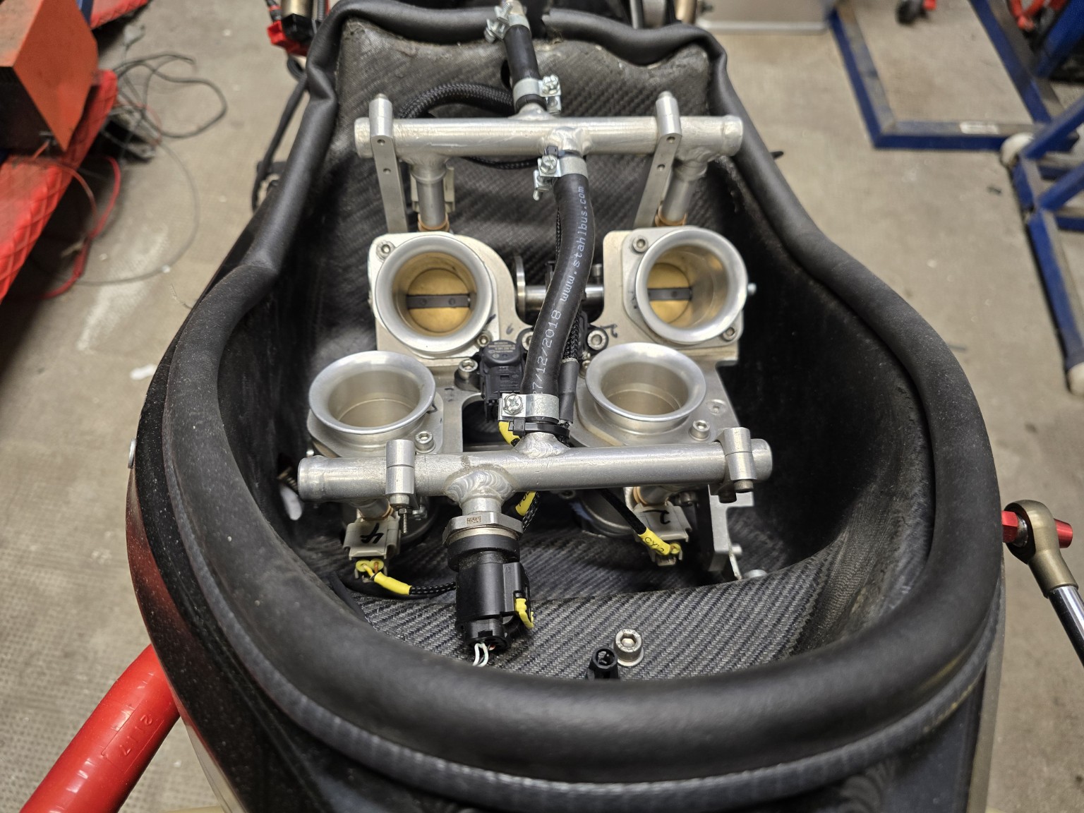
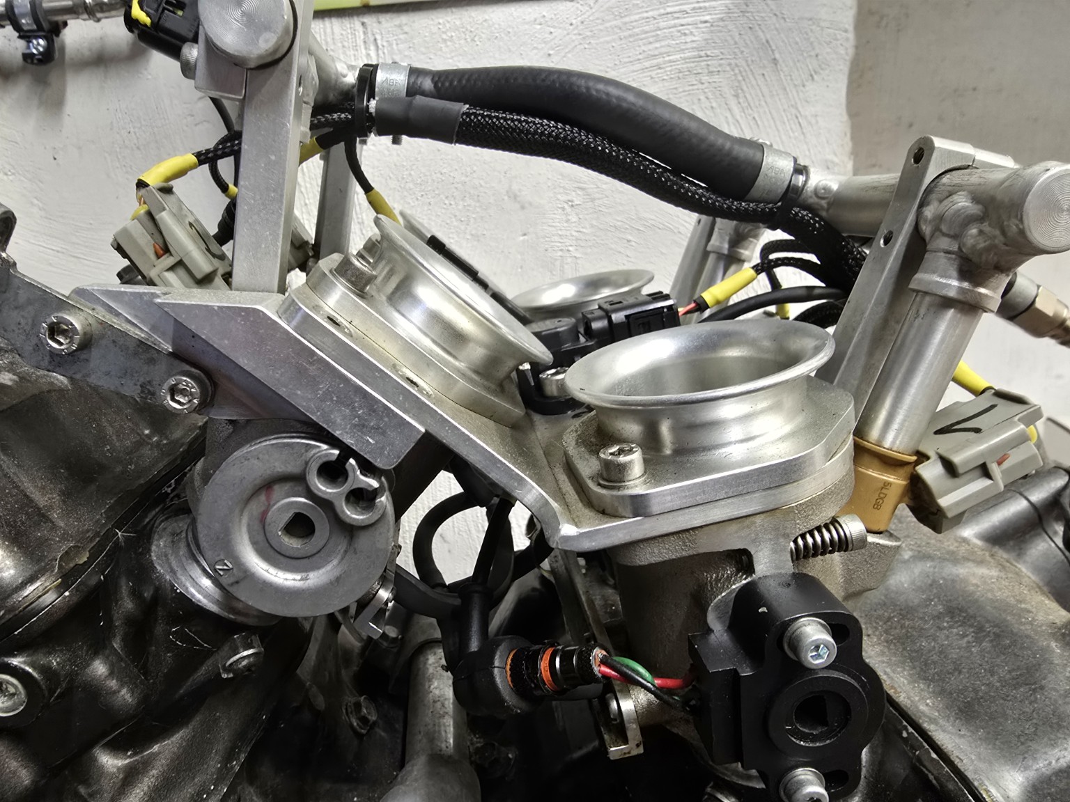
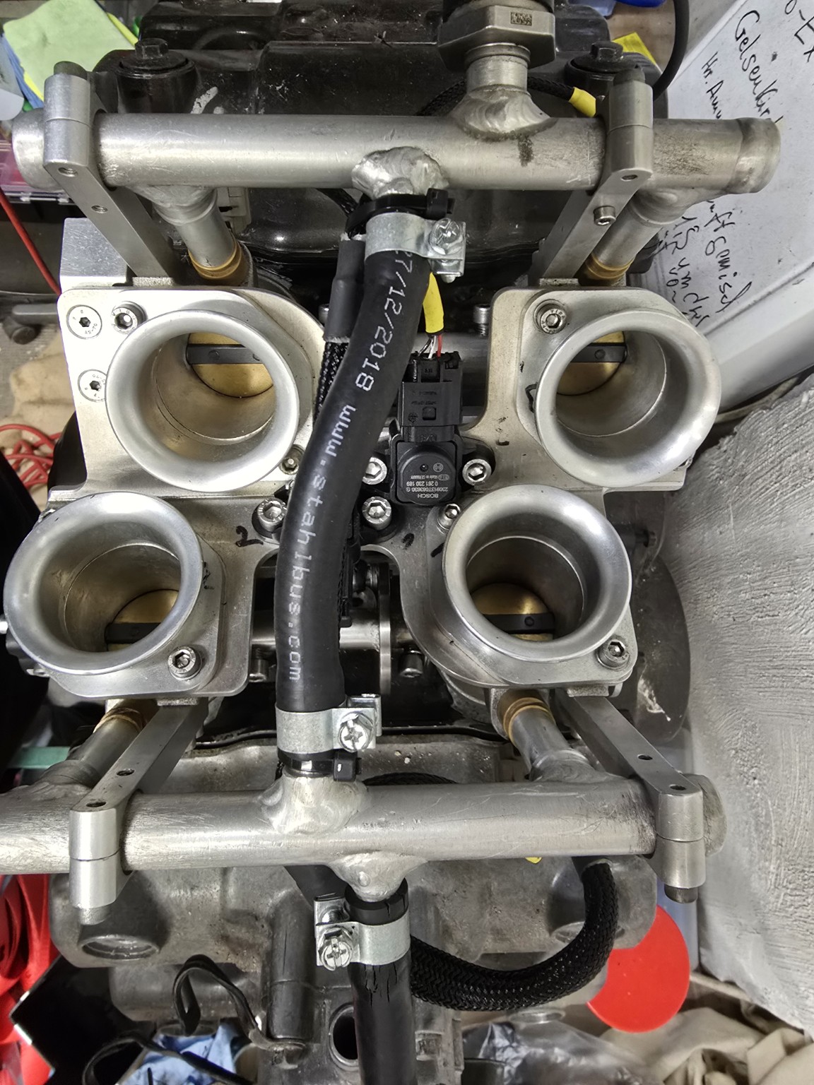
The original carburettors were replaced with four custom-made throttle bodies from Jenvey Dynamics in England. Each has a 34 mm bore and a 20 mm intake trumpet.
Engine management and fuel supply
| Component | Specification |
|---|---|
| ECU | MoTeC M800; the conversion concept can also be implemented with M400, M880 or M130 |
| Fuel pump | Honda CBR600RR PC40, installed inside the RVF400 tank |
| Current fuel pressure | 3.7 bar |
| Current injectors | Yamaha YZF-R6 |
| Previous injectors | Honda CBR600RR PC40 |
The Yamaha R6 injectors are slightly longer than the previously used PC40 injectors, extending further into the custom Jenvey throttle bodies.
Fully sequential injection and sensors
The original Honda crankshaft sensor is retained with a modified trigger wheel. A camshaft sensor provides engine phase information for fully sequential injection. The system also uses a throttle position sensor (TPS), an airbox pressure sensor and two manifold pressure sensors connected directly below the throttle plates.
| Pressure sensor | Measurement |
|---|---|
| Manifold pressure 1 | Cylinders 1 and 3 |
| Manifold pressure 2 | Cylinders 2 and 4 |
| Airbox pressure | Airbox pressure signal used in fuel calculation |
Ignition
The initial setup used the original Honda ignition coils with a Bosch ignition module. The current setup uses Honda CBR600RR PC40 stick coils, which fit the RVF400 spark plug wells without mechanical modifications. The MoTeC M800 controls injection and ignition, with a MoTeC IGN4 driving the ignition coils.
Individual-cylinder lambda monitoring
Lambda monitoring evolved from one Bosch LSU 4.9 sensor at the end of the exhaust, to separate sensors for cylinder groups 1/3 and 2/4, and finally to one wideband sensor per cylinder. The current setup uses four Bosch LSU 4.9 sensors, two MoTeC LTC-D controllers and CAN communication with the M800.
Custom carbon-fibre airbox and ram-air
The airbox was designed with a friend and first laminated in fibreglass (GRP); the design was subsequently reproduced in carbon fibre. Its air routing follows the Honda RC45 concept: air enters through the front fairing and travels through two ducts above the tank to the airbox. The airbox is not fully sealed. Its pressure is measured separately and used in the fuel calculation.